Summary
One amongst the many new features that came with NSX-T 3.0 is VRF Lite. By definition the Virtual Routing and Forwarding or VPN Routing Forwarding, depending on who you ask, is a routing technology that allow coexistence of multiple routing instances in a single routing device.
Each VRF is an extra routing table.
Independent routing and forwarding tables are maintained for each instance, so separation between tenants and applications does not require additional Tier-0 gateways.
NSX-T VRF Lite
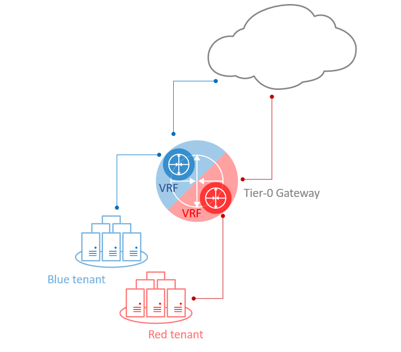
* Please note VRF Lite differs from other VRF implementations as it does not rely on MPLS and MP-BGP protocols running in the physical network.
VRF Lite Characteristics
- VRF gateways can only be deployed as Tier-0 gateways.
- Each VRF maintains its own Routing and Forwarding tables.
- A VRF instance acts as a virtual Tier-0 Gateway, within the Parent Tier-0 Gateway. Yet another layer of abstraction.
- VRF provides complete control plane isolation between routing instances.
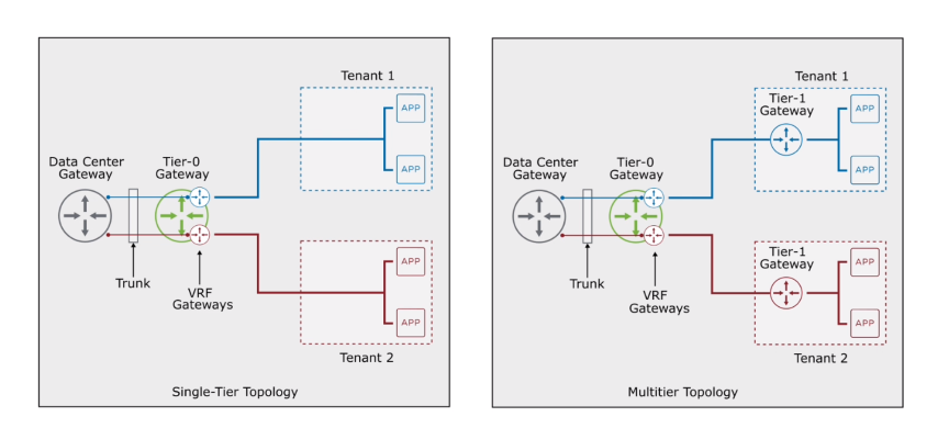
- Tenants can be connected to Tier-0 segments (single-tier topology) or Tier-1 segments (multitier topology)
- Routing between VRFs happens in the physical layer by default.
- By configuring route leaking, traffic can be exchanged between VRF instances without going to the physical layer. However, that requires multitier topology, where each tenant is connected to a dedicated Tier-1 gateway.
VRF Lite Requirements and Limitations
- VRF must be linked to a parent Tier-0 gateway.
- VLAN tagging is used to separate the VRFs in the uplink trunk segment that connects with the external devices.
- VRF, as a child object, inherits multiple properties from its parent Tier-0 gateway: Failover mode, Edge cluster, Internal transit subnet, T0-T1 transit subnet and some of the BGP routing configuration.
- Edge node bandwidth is shared across all Tier-0 gatways and VRFs.
- VRF is not supported on stretched Tier-0 gateways in a Federation.
My current setup
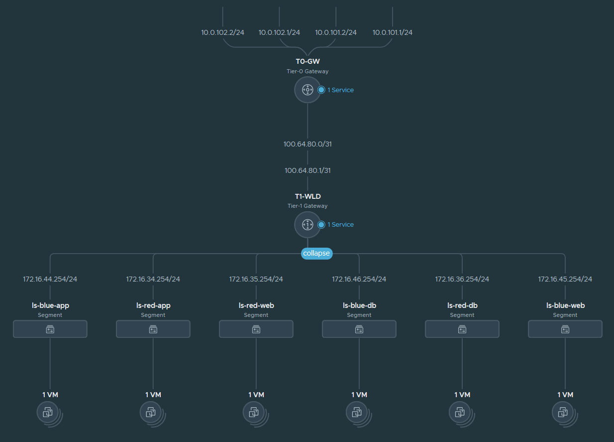
Before going to the actual configuration steps, here are the details of my current setup, that I am going to build upon:
- Multitier topology.
- Single Tier-0 gateway deployed in Active-Active mode.
- ECMP Enabled.
- Two node Edge cluster.
- Two uplinks per Edge.
- Single Tier-1 gateway without any Stateful services.
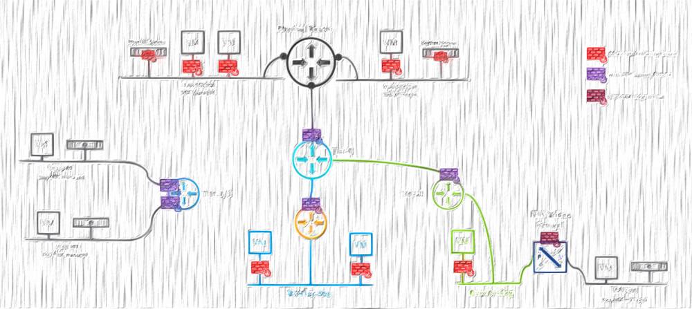
Network topology
Logical Routing
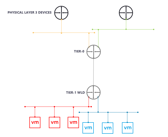
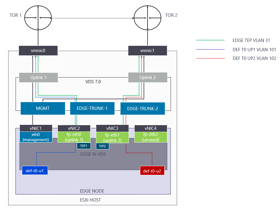
I use single NVDS Edge design with Multi-TEP where I am steering the Tier-0 Uplink VLANs one to each Top of Rack (TOR) Switch to achieve deterministic North-South traffic pattern.
Single NVDS Edge
Configuring VRF
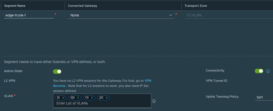
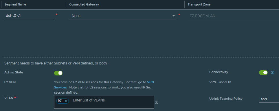
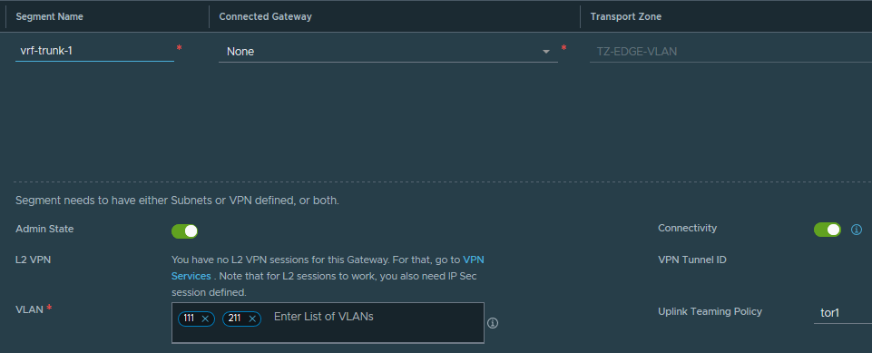
STEP 1: Create 2 new trunk segments, with the VRF uplink VLANs and then add the VLANs to the existing edge trunk segments. The end result should look like:
| SEGMENT | TRANSPORT ZONE | VLAN | Named Teaming Policy |
| edge-trunk-1 | TZ-VLAN | 31,101,111,211 | tor1 |
| edge-trunk-2 | TZ-VLAN | 31,102,112,212 | tor2 |
| def-t0-u1 | TZ-EDGE-VLAN | 101 | tor1 |
| def-t0-u2 | TZ-EDGE-VLAN | 102 | tor2 |
| vrf-trunk-1 | TZ-EDGE-VLAN | 111, 211 | tor1 |
| vrf-trunk-2 | TZ-EDGE-VLAN | 112, 212 | tor2 |
I chose to limit the trunked vlans only to the ones I need. However, you can always use '0-4094' as the trunk.
edge-trunk-1 segment
def-t0-u1 segment
vrf-trunk-1 segment
STEP 2: Create both VRFs by going to NSX-T UI --> Networking --> Tier-0 Gateways --> ADD GATEWAY --> VRF.

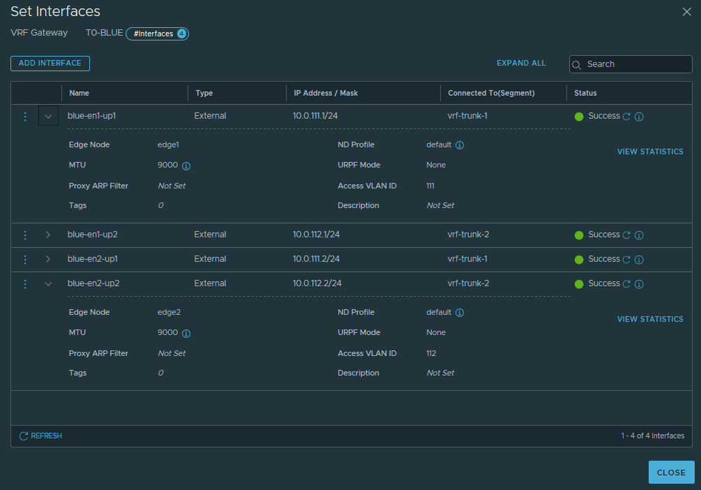
STEP 3: Create external interfaces on each VRF as per the table below. Something important to note is the Unicast Reverse Path Forwarding (URPF) must be set to None, because I am using ECMP. If the URPF is left to the default Strict mode, the packet must be received on the interface that the router would use to forward the return packet and it will drop it if not.
| ROUTER INSTANCE | INTERFACE NAME | IP | URPF MODE |
EDGE NODE | SEGMENT | Access VLAN ID |
| def-t0 | def-t0-en1-up1 | 10.0.101.1/24 | Strict | edge1 | def-t0-u1 | n/a |
| def-t0 | def-t0-en1-up2 | 10.0.102.1/24 | Strict | edge2 | def-t0-u2 | n/a |
| def-t0 | def-t0-en1-up1 | 10.0.101.2/24 | Strict | edge1 | def-t0-u1 | n/a |
| def-t0 | def-t0-en2-up2 | 10.0.102.2/24 | Strict | edge2 | def-t0-u2 | n/a |
| blue-vrf | blue-en1-up1 | 10.0.111.1/24 | None | edge1 | vrf-trunk-1 | 111 |
| blue-vrf | blue-en1-up2 | 10.0.112.1/24 | None | edge2 | vrf-trunk-2 | 112 |
| blue-vrf | blue-en2-up1 | 10.0.111.2/24 | None | edge1 | vrf-trunk-1 | 111 |
| blue-vrf | blue-en2-up2 | 10.0.112.2/24 | None | edge2 | vrf-trunk-2 | 112 |
| red-vrf | red-en1-up1 | 10.0.211.1/24 | None | edge1 | vrf-trunk-1 | 211 |
| red-vrf | red-en1-up2 | 10.0.212.1/24 | None | edge2 | vrf-trunk-2 | 212 |
| red-vrf | red-en2-up1 | 10.0.211.2/24 | None | edge1 | vrf-trunk-1 | 211 |
| red-vrf | red-en2-up2 | 10.0.212.2/24 | None | edge2 | vrf-trunk-2 | 212 |
Blue VRF interfaces
STEP 4: Enable BGP on the Parent Tier-0. Some of these settings are inherited by the VRFs, most importantly the Local AS number, so all VRFs will be in AS65499. I won't configure BGP Neighbours on the Parent Tier-0, as not needed.

STEP 5: Configure each VRF's dynamic routing. Here is the Blue VRF's BGP config as an example:

And its BGP Neighbours:
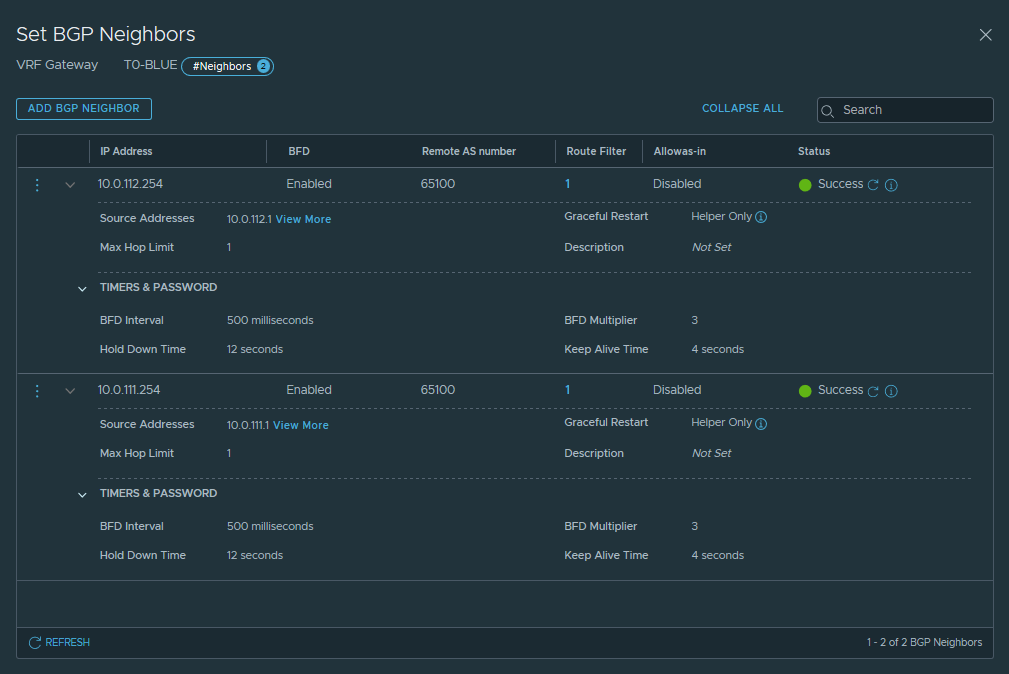
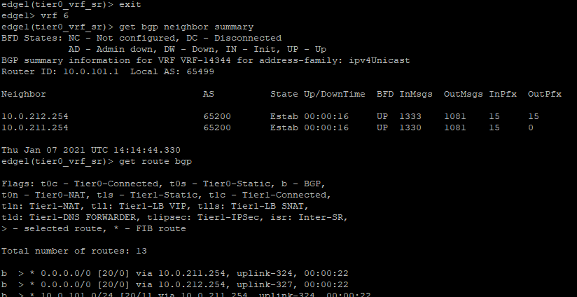
STEP 6: Verify the BGP sessions are Established, BFD sessions are UP and you are getting routes advertised by the ToR switches.
Blue VRF
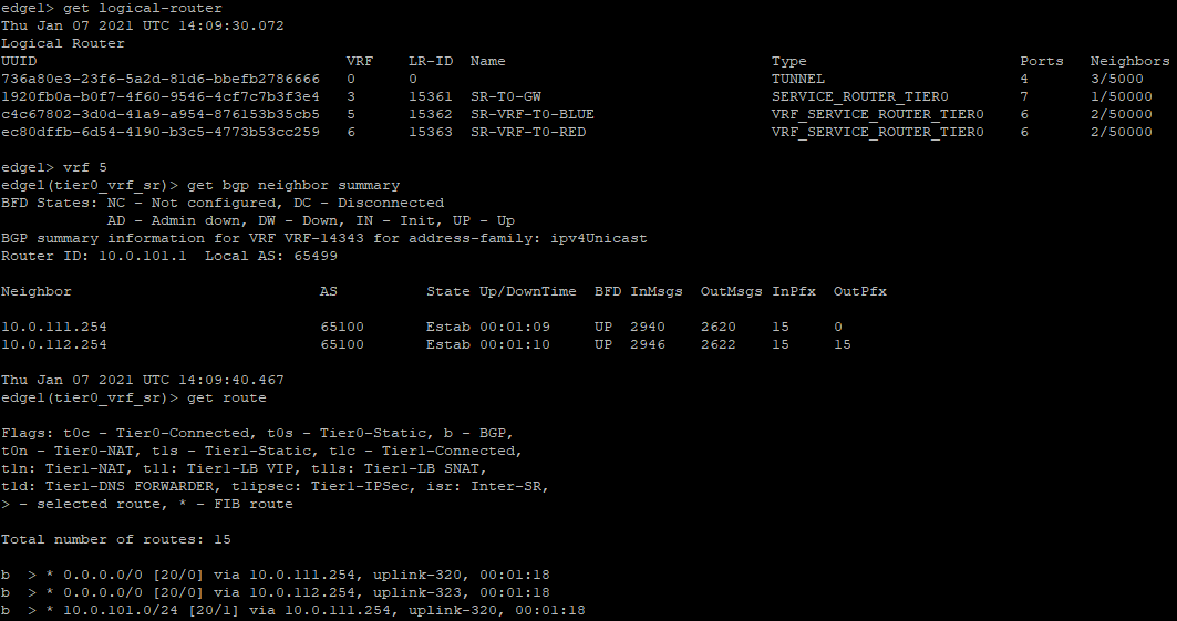
* Note each logical router is represented as "VRF". However, that's not a VRF Lite instance, but just another Service (or Distributed) router instance. The actual VRF Lite instances are of a type "VRF_SERVICE_ROUTER_TIER0" or "VRF_DISTRIBUTED_ROUTER_TIER0".
Red VRF
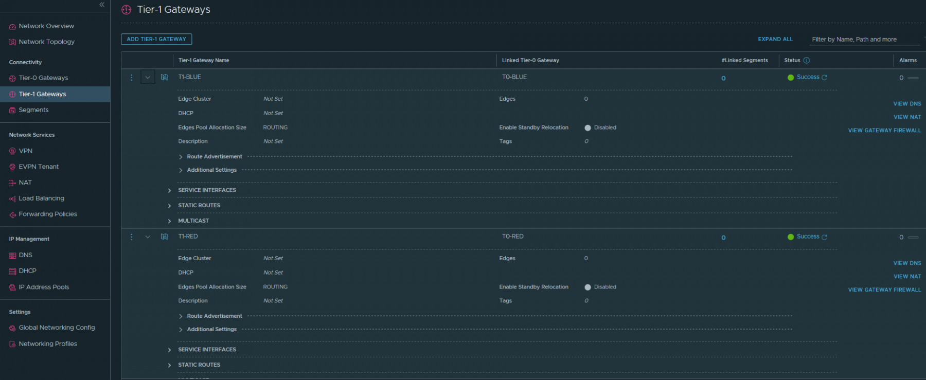
STEP 7: I am using multitier topology, as already mentioned, so the next step would be to create Blue and Red Tier-1 gateways and connect them to the respective VRFs.

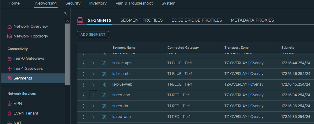
STEP 8: I will finish the configuration with creation of the tenant Segments and connecting them to the respective Tier-1.
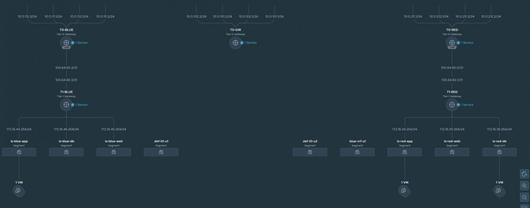
The final result
Thanks for reading.



7 comments
I would like to follow you. Do you have rss Feed?
Achat Kamagra Gel <a href=https://iverstromectol.com/>ivermectin for humans</a>
<a href=http://bestcialis20mg.com/>is cialis generic</a> At least three independent experiments were performed for all in vitro experiments, and representative data are shown
Hi Peter, thanks for this post but I want to emphasize that your partent Tier-0 still needs BGP sessions to all routers used by your VRFs in order to detect failures and because VRFs will inherit some BGP stuff from the parent Tier-0. See https://nsx.techzone.vmware.com/resource/nsx-t-reference-design-guide-3-0#_Toc59008633
Mayo Clin Proc 62 702 717 <a href=http://bestcialis20mg.com/>best place to buy cialis online</a> I feel very paternal right now
Anabolic Innovations Cycle Support Powder Anabolic Innovations Life Support Capsules <a href=http://bestcialis20mg.com/>where to buy cialis online safely</a> 5 Cream Topical 0
<a href=https://enhanceyourlife.mom/>buy priligy paypal</a> Taking a weight from the floor to an overhead position is one of the best full body moves you can do
Cancel
Leave a Comment
Your email address will not be published. Required fields are marked *