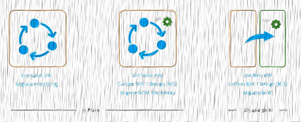
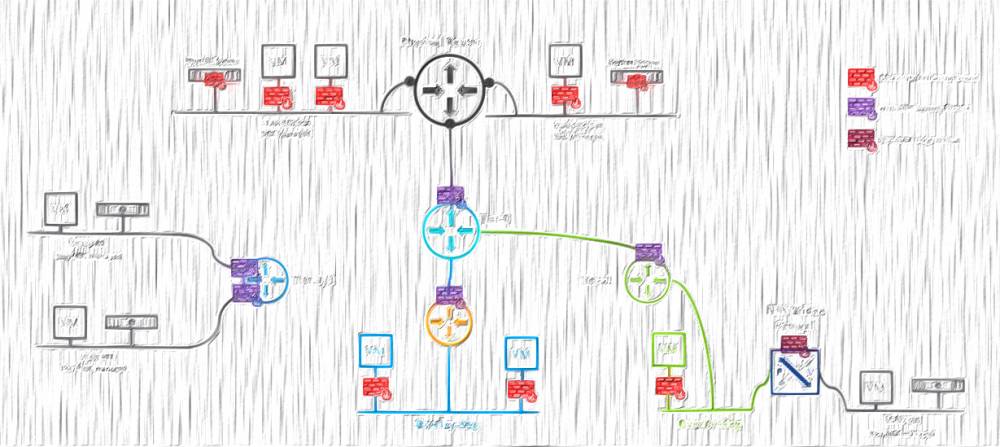
In the first part of these series, I described the overall design of the V2T.DEMO lab. In this one I covered the pfSense configuration, that is meant to provide the layer 3 services to my environment.
Building up nested V2T demo environment - PART1: Overview
Building up nested V2T demo environment - PART2: pfSense (this article)
Building up nested V2T demo environment - PART3: TrueNAS
Please note that is not a pfSense how-to article, so I am not going to go into step-by-step details on how to install and configure it. I will rather focus on the specific configuration that allows pfSense to provide L3 services to my nested lab. If you look for a detailed documentation on the pfSense installation and confgiuration, please click here.
pfSense configuration
For the pfSense installation I am going to need one NSX-T overlay Segment and one distributed port group. The NSX-T Segment is connected to a tier1 gateway on my underlying physical environment. That is where I will connect the WAN interface of the pfSense to.
The LAN interface of the pfSense appliance, will be connected to a trunk (0-4094) distributed port group. The reason behind using a portgroup and not an nsx segment is because I must enable Promiscious mode on it. NSX Segments do not support promiscious mode, hence I will use a distributed port group. The need behind the promiscious mode is so the pfSense's LAN interface can intercept every single packet sent to that portgroup and thus provide L3 services to the underlying VMs.

STEP 1: define WAN and LAN interfaces
After the pfSense is installed, configure vmx0 (connected to the NSX-T Segment) as WAN and vmx1 (connected to the Trunk pg) as LAN. It should look like that (10.2.11.2 is the uplink IP of my pfSense):

STEP 2: Disable pfSense firewall on the WAN interface
At his point we will not be able to reach the webConfigurator tool on the uplink address, because pfSense has a firewall rule which drops all the traffic on the WAN interface by default. To overcome that we will need to add a temporarily Allow rule on the WAN interface, to let us in and configure the virtual router settings via web.
To add an "allow all" rule to the WAN interface, run the following command at the shell prompt:
# pfSsh.php playback enableallowallwan
(I have fully configured distributed firewall on the upstream NSX-T environment, so I won't even bother to delete that rule afterwards. It is up to the specific case if you want that rule gone or not, so consider that carefully.)
Now we should have access to the pfSense web interface, that we gonna utilize to further configure the pfSense appliance.
STEP 3: Change Admin password
Change the default admin password (System / User Manager/ Users / Edit)
STEP 4: Add a DNS server
Add a DNS server, cause you gonna need it in the following steps. (System / General Setup)
STEP 5: Install VMware tools
Install open-vm-tool package to add the required drivers and enhance the performance of the appliance. (System / Package Manager / Available Packages)
STEP 6: Install FRR
Install FRR to allow BGP peering (and OSPF if needed) with the NSX environment. (System / Package Manager / Available Packages).
Installed Packages

STEP 7: Create VLANs
Create the necessary VLANs. All the VLAN interfaces must use the LAN interface as a parent. (Interfaces / VLANs)

* Please note these VLANs must be trunked on the physical switch ports, that are facing the physical esxi hosts (alternatively, if you don't have an access to the physical switches, you must keep all the nested esxi hosts to a single physical esxi, to ensure no nested traffic is crossing the physical switches).
STEP 8: Create new interfaces
Create new interfaces and map them to the VLANs. (Interfaces / Interface Assignments).
I am not going to use the native VLAN on the LAN interface, so I am actually going to set VLAN 501 and rename the interface to MGMT for clarity... and this is where I ran into the first issue - when I tried to change the LAN interface I've got an error:

That error is pretty much self explanatory. What you need to do is to enable Static IPv6 on the LAN interface and set the IP to ::1/128. Then switch and set the Router mode to Disabled. (Services / DHCPv6 Server & RA / LAN / Router Advertisements)
Go back to the LAN interface's settings, where you have to disable IPv6 and configure a static IPv4 address - the gateway of that particular VLAN. I will set the MTU to 9000 (Optional).

The above configuration, with the respective unique Static IPv4 addresses, must be done on each one of the VLAN interfaces. That is how the final result looks like:

STEP 9: Allow traffic in the firewall
The final step from the initial pfSense configuration is to create ANY-ANY-ALLOW rule on all the newly created interfaces. (FIREWALL / Rules / Interface name):

Quick hint on this step - there is a copy icon in the list of rules, so once you create the any-any-allow rule on your first interface, you can easily copy it to rest interfaces.
STEP 10: Enable FRR
The first step, from the dynamic routing configuration, would be to enable the the FRR/Zebra instance. Navigate to Services / FRR Global/Zebra, tick the Enable FRR option, set the default router ID (I use the IP assigned on the WAN interface) and a password. Do not worry about the complexity (or visibility) of that password, as it is used internally only.

Hit Save, at the bottom of the page and proceed to the next step.
STEP 11: Configure BGP
Go to Services / FRR BGP and check the Enable BGP Routing option. Set a Local ASN, and the desired BGP Timers. There is no need to set the Router ID once again, just leave it blank and it will use the global one, set in the previous step.

While we are still on the same page, scroll down to the Network Distribution section and enable redistribution of the connected networks and kernel routing table into BGP.

Hit Save at the bottom of the page and proceed.
STEP 12: Create Prefix List
The official FRR documentation says, that if no prefix list is defined the default behaviour is permit. However, the FRR implementation in pfSense says the opposite: Inbound/Outbound updates discarded due to missing policy.

Now, as we know that we must create such policy, navigate to Services / FRR Global/Zebra / Prefix Lists and add a new Prefix List.
I want to receive and advertise all IPv4 networks, so I will set Permit and select Any network. The sequence is also important, as it indicates the order in which the Prefix Lists will be applied. In my case I have just that single prefix, hence setting a sequence of 1 is fine.

STEP 13: Add BGP Neighbours
Navigate to Services / FRR BGP / Neighbours and Add your BGP Neighbours. In this instance that would be both interfaces of the NSX-V ESG only, because my WAN interface is connected to the upstream NSX-T tier1, so no dynamic routing is needed there. Feel free to add an upstream neighbour if your environment allows that.
There are few sections, of the Neighbour's config, that have to be set. First is the General Options, where I am going to define the IP address and the Name:

Then comes the Basic Options, where I need to set the Remote ASN and also to enable Default Originate (so the pfSense can advertise a default route towards the bgp neighbour). There is an option to define custom BGP timers, or just leave blank if you prefer to use the global values, that we configured previously.

On the Peer Filtering field is where I will define the previously created Prefix List filter, to allow inbound and outbound IPv4 advertisements.

There are some more useful options in the other sections, like BFD (which has to be enabled when we finish the V2T migration, cause NSX-T needs it) or a custom local ASN, so you set them if needed.
Repeat the above for as many BGP neighbours you want to configure. As soon as you hit Save it should establish a BGP session, given you have preconfigured BGP neighbours on your NSX-V ESGs.
That concludes the pfSense for NSX configuration.
Thanks for reading.


6 comments
Just wanted to thank you for this. Been trying to get NSX-T up in home lab using pfSense router for BGP. The stuff here really helped.
Hi Mike,
I am happy to know you've found it useful.
Cheers,
Peter
thank you very much, really helped me!
<a href=http://clomid.mom/>buy clomid</a> Peter Oppenheimer, Apple s chief financial officer, said the company will have a very busy fall, though he declined to elaborate
12/15
I heard what you need to say! You raise a great point and I've pondered exactly the same thing. I think remarks are certainly heard in any event, when it is a bustling discussion. Regardless of whether the creator have the transfer speed to answer each and every remark, other analysts that are bought in can bounce into the discussion like you and I are doing now. https://joinlive77.com/
<a href=https://bestcialis20mg.com/>best price for generic cialis</a> I am wearing a pad now again just to observe
Cancel
Leave a Comment
Your email address will not be published. Required fields are marked *